Abstract
Underground coal mining is impossible without the use of protective pillars or protective isolation walls. Regardless of the method of coal mining (longwall method, room and pillar etc.), they all require the use of pillars or protective isolation walls. Their application is present in the exploitation of all types of coal. Today, the design of pillars and protective isolation walls is carried out in the same way. All of them, regardless of their physical and mechanical properties or the applied excavation method, undergo changes over time. Changes can occur due to mechanical damage (mining, rockfall, vibrations due to transport, gas outbursts, etc.) or due to the influence of the pit ventilation system. Although the influence of the ventilation system of the pit on the protective insulation walls is established and known, it has been very little addressed and treated in the literature or concrete research. After the formation of a pillar or isolation wall, under the influence of the pit ventilation system, moisture and gases begin to be released from it, and the cohesive and adhesive forces in it weaken, which also leads to rheological changes. It has been established that in isolation walls where moisture is periodically or constantly introduced and increased for some reason, most often in order to eliminate coal dust, the intensity of rheological changes is lower than in those where this is not done. The paper presents the results of research into the changes that occurred in protective insulating walls used in brown coal mining due to the influence of the pit ventilation system over a certain period of time. Changes in the design of protective columns and insulating walls, taking into account the influence of the pit ventilation system on them, are also proposed.
Keywords
Pit Ventilation System, Protective Isolation Wall, Coal
1. Introduction
When we talk about protective pillars, we must distinguish between pillars that are used exclusively as a support for roof layers and protective isolation walls that are used to physically separate individual parts or areas in an underground mine. Both are designed in the same or similar way today and represent part of the unexcavated coal mass.
Isolation walls in underground coal mines have two functions. They isolate and physically separate the hollows from the active parts of the pit and serve as load-bearing protection for the mining rooms. Or, they serve to separate different air currents (fresh and return) and as load-bearing protection for the mining rooms through which the air moves.
After the formation of the isolation wall, which has covered part of the coal seam, moisture and gases begin to separate from it, the adhesion and cohesion forces in the coal material from which it is built weaken.. Conditions are created for increasing its porosity and permeability, which ultimately leads to rheological changes
| [1] | T. Yang, Y. Zhang and other: “Study on the Stability and Reasonable Width of Coal Pillars in “Three Soft” Coal Seams Based on a Physical Similarity Simulation Experiment”, Applied Sciences, Volume 14, Issue 14, 2024.,
https://doi.org/10.3390/app14146127 |
[1]
. The rate and amount of moisture that will be extracted from the protective isolation wall depends on:
1) the initial waterlogging of the coal seam,
2) the porosity,
3) the position in the ventilation system,
4) the proximity of the fire zone,
5) the exposure to the potential difference, etc.
The rate and amount of gases extracted from the isolation wall depend on their content in the coal seam, gas-bearing capacity of the coal seam, as well as other ventilation parameters (potential, volume flow, etc.)
| [2] | L. Dai, H. Lei, X. Cheng, R. Li: “Prediction of coal seam gas content based on the correlation between gas basic parameters and coal quality indexes”, Frontiers Energy Research, Volume 10, 2022., https://doi.org/10.3389/fenrg.2022.1096539 |
[2]
. Moisture is present in all coals, and due to its extraction from the isolation wall, conditions are created for increasing its permeability, and ultimately conditions are created for heating and self-ignition of the coal
| [3] | J. Marković, S. Mićević: “Požari u rudnicima uglja” [Fires in coal mines], UNTZ, Tuzla 2005. |
[3]
. This phenomenon is present in all coals and isolation walls and can only be more or less intense and pronounced.
In order to determine the functional dependence between the service life of a protective isolation wall and changes in the magnitude of physical and geomechanical properties in it (moisture content, porosity and cracking, rheological changes), research was carried out on real samples, i.e. on several isolation walls that have different service lives and were formed in the same working environment.
1.1. Methods for Designing Pillars and Isolation Walls
Protective pillars play an important role in underground coal mining. The deformation-stress characteristics of the part of the rock mass surrounding the underground space depend on their dimensions, shape and load-bearing capacity. The load on protective pillars changes depending on the distance from the excavated space and the width of the pillar
| [4] | V. R. Sastry: “Stress distribution on longwall barrier pillar due to goaf formation during extraction”, Journal of the Institution of Engineers, India, Mining Engineering Division, 2009. |
[4]
. The study of the load on protective pillars is of great importance, especially due to the choice of its dimensions (w-width, l-length) and the deformation-stress state in the mass of the pillar itself. Protective pillars are divided according to the dimensions of the base into
| [5] | Z. Benjavski: ” Upravlenie gornim davleniem”, Moskva 1990. |
[5]
:
1) protective pillars in the form of a protective isolation wall of great length, provided that l/w>3,
2) protective pillars in the form of a protective wall of small length, provided that l/w>1-3,
3) protective pillars in the form of a pillar, provided that l/w=1.
Calculating the dimensions of pillars is an extremely complex task
| [6] | G. York, I. Canbulat, B. W. Jack: “Coal pillar design procedures”, Safety in Mines Research Advisory Committee, Mine Health and Safetv Council, March 2000. |
[6]
. There is no universal approach and patterns for dimensioning pillars and there are no universal methods and principles for their design
| [7] | R. N. Singh, A. G. Pathan, B. Unver: “Design of rib pillars in longwall mining based on theoretical and practical approaches”, Maden Muhendisleri Odasi, 1987. |
| [8] | H. Wagner: “Pillar design in coal mines”, Journal of the South African Institute of Mining and Metallurgy, January 1980., 37-45. |
[7, 8]
.
Today, we encounter several ways of dimensioning pillars, which can be classified into several basic groups
| [9] | J. N. van der Merwe: “Develop intrnational links for co-operative research in coal mining with special emphasis on interaction with international experts for developing industry guidelines for the design of pillars in coal mines”, Safety in Mines Research Advisory Committee, Mine Health and Safetv Council, July 2001. |
[9]
:
1) empirical (experienced) methods,
2) numerical (analytical) methods,
3) ALPS US methods,
4) ALTS Australian methods,
5) hybrid methods.
Empirical methods are still the most widely used due to their reliability, the ability to connect multiple factors such as the role of geology, the quality of coal in the pillar, the shape of the pillar, the relationship between safety and the possibility of destruction, experience in application, etc. The most significant empirical patterns were given by Salamon-Galvin
| [10] | J. M. Galvin, B. K. Hebblewhite, M. D. G. Salamon: “University Of New South Wales Coal Pillar Strength Determinations For Australian And South African Mining Conditions”, National Institute for Occupational Safety and Health (NIOSH), CDC STACKS, 1999. |
[10]
, Mark-Bieniawsk
| [11] | Z. T. Bieniawski: “A method revisited: coal pillar strength formula based on field investigations”, Proceedings of the workshop on coal pillar mechanics and design, US Bureau of Mines IC 9315 1992. |
[11]
, Merwe
| [12] | J. N. van der Merwe: “New pillar strength formula for South African coal”, Journal of the South African Institute of Mining and Metallurgy, June 2003., 281-292. |
[12]
and others.
As for numerical (analytical) methods, they include models that, in addition to the geometry of the pillar, also take into account geology, strength, bottom-to-roof contact and some other parameters. The most famous models of numerical methods are FLAC (Fast Lagrangian Analysis of Continua), FESOFT and LAMODEL. FLAC
| [13] | K. Oraee, N. Hosseini, H. Yasipur: “Logical design of yield pillar base in longwall mining”, Seventeenth international symposium on mine planning and equipment section, Beijing, China, 2008. |
[13]
is a software based on the finite element method and takes into account coherence, friction and flow during plastic deformation in the protective pillar sample.
Hybrid methods are actually a combination of numerical models associated with empirical patterns. ALPS and ALTS methods are used more in calculations during tunnel construction.
Today, the trend in the world is to dimension the pillars using some of the empirical methods, and then check the obtained dimensions using analytical or hybrid methods, but there are also some new approaches in the design of pillars
| [14] | E. Ghasemi, K. Shahriar: “A new coal pillars design method in order to enhance safety of the retreat mining in room and pillar mines”, Safety Science, Volume 50, Issue 3, March 2012, Pages 579-585, https://doi.org/10.1016/j.ssci.2011.11.005 |
[14]
.
1.2. Location and Research Objective
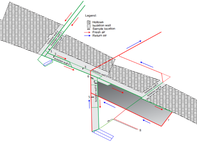
The study of the influence of the pit ventilation system on changes in the protective isolation walls was carried out in the RMU “Banovići” pit (www.rmub.ba) where brown coal is excavated using the longwall method. The pillars used in the RMU “Banovići”, and given the applied method of coal excavation, have the exclusive function of isolation walls. As isolation walls, they separate the active parts of the pit from the hollows (excavated areas) and separate the air currents (incoming fresh and return) in individual districts or excavation fields.
Figure 1. Arrangement of isolation walls and sampling locations.
Isolation wall 1,
Figure 1, was formed by creating two rooms through which fresh air is introduced into the pit. A system for transporting coal from the pit using rubber belt conveyors was installed in one of these two rooms. In order to prevent the deposition of hazardous coal dust in this room, it is regularly, weekly, moistened with water, i.e. the deposited coal dust is washed out of it. This wetting of the isolation wall has caused it to remain almost completely undamaged even after 40 years, despite the vibrations caused by coal transport. The other side of isolation wall is not wetting and in this part of the wall its destruction is noticeable to a depth of 2.5 m. This difference in the condition of the isolation wall and the level of its destruction has led to an examination of the condition of the other isolation wall in the pit, as well as the causes that lead to changes in them.
1.3. Research Method
Includes In situ methods:
1) measurements of ventilation parameters and potential distribution in active mining rooms and the hollows under normal ventilation regime conditions and when changing the ventilation regime.
2) Laboratory methods:
3) taking and preparing samples of isolation walls (by coring) and reference samples (by channel sampling),
4) testing and laboratory analysis of samples,
5) monitoring of gas state and potential in sampling wells.
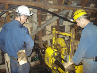
Coal sampling from isolation walls was carried out by coring. Drilling was carried out at six locations. The sample was taken from the isolation walls at a depth of 3 (m) and 10 (m). The reason for this choice of the depth at which the sample is taken is that at some sampling locations at depths smaller than 3 (m) the coal layer is already so destroyed that it is impossible to take a quality sample and that the depth of 10 (m) actually already represents half the width of the isolation walls. After taking the samples, the sampling well is hermetically closed and the pipe is left for taking air samples from the well in order to measure the potential and gas relations. In two places, for taking reference samples of the coal seam, the samples were taken by channel.
Figure 2. Coal sampling from a isolation wall by coring.
Sampling location (1) is in the incoming fresh air stream. The side of the room is extremely dry and disturbed to a depth of 2.2 (m). Sampling location (2) is in the fresh air stream. The side of the room is extremely dry. The isolation wall is severely disturbed to a depth of 2 (m). Sampling location (3) is in the fresh air stream. The side of the room is slightly damp, and the isolation wall is disturbed to a depth of 0.5 (m). Sampling location (4) is in the fresh air stream. The side of the room is extremely dry, and the isolation wall is disturbed to a depth of 0.2 (m). Sampling location (5) is in the return air stream. The side of the room is dry, and the isolation wall is intact. Sampling location (6) is in the return air stream. The side of the room is extremely damp, and the isolation wall is intact. Sampling location (7) is in a longwall (reference sample). The sample was taken with a channel at a depth of 0.3 (m). The side of the room is extremely dry and undamaged. The location of sampling (8) is at the workplace of the preparation room. The sample was taken with a channel at a depth of 0.3 (m) (reference sample). The sampling location is dry and compact.
The following Table shows the microclimatic conditions at the sampling locations.
Table 1. Microclimatic conditions at sampling locations.
Sample location | Airflow speed (m/s) | Volumetric flow (m3/s) | Relative humidity (%) | Temperature (°C) | Age of wall (years) | Comment |
1 | 2,04 | 13,23 | 81 | 4 | 40 | Flow ventilation |
2 | 1,25 | 11,23 | 82 | 4 | 30 |
3 | 0,17 | 1,5 | 87 | 8 | 30 |
4 | 0,33 | 3,33 | 93 | 11 | 25 |
5 | 0,28 | 2,8 | 94 | 18 | 25 |
6 | 1,97 | 24,43 | 100 | 21 | 25 |
7 | 0,86 | 5,4 | 95 | 22 | 0 |
8 | - | - | 93 | 19 | 0 | Diffusion ventilation |
2. Research Results
In order to determine the intensity of changes in the isolation walls caused by the pit ventilation system, it is necessary to know:
1) the state of the isolation wall in the formation phase (its properties in the formation phase that are affected by ventilation),
2) how the pit ventilation system affects the isolation wall (what the change leads to),
3) the intensity of the influence of the pit ventilation system on the isolation wall (the location of the isolation wall in the pit ventilation system),
4) the intensity of changes in the isolation wall caused by the pit ventilation system.
In order to determine the influence of the pit ventilation system on the isolation walls, it is necessary to know the state of the isolation wall in the formation phase. For the isolation walls at the research location, this is technically not possible to determine, since the isolation walls have been in use for a long time. What can be done is to examine the quality, or certain properties of the coal seam whose position in the coal seam corresponds to the position of the isolation walls and which was not exposed to any influence of the pit ventilation system (locations 7 and 8,
Figure 1). In this sense, a sampling of the part of the coal seam on which the pit ventilation system had no or very little influence was carried out (reference samples).
The properties of the isolation walls that were the subject of the test are:
1) humidity,
2) gas ratios,
3) porosity and cracking testing,
4) intensity of destruction.
The pit ventilation system acts on the isolation wall:
1) thermally,
2) mechanically.
The thermal effect is manifested through the release of moisture from the isolation wall and its absorption by the air current. The air current takes up part of the moisture from theisolation walls and exhausts it outside the pit through the ventilation system. By releasing moisture from the cracks in the isolation wall, conditions are created for deeper air penetration into it and its further "drying". The intensity of moisture uptake from the isolation walls by the air flowing through the room depends on its temperature and humidity. The warmer and drier the air is, the more moisture it absorbs, and conversely, the colder and more humid it absorbs less or almost no moisture.
The mechanical effect is manifested through the action of the forces of air currents. In this way, the isolation walls is slowly destroyed and the destruction is slower towards the middle of the isolation walls. The reason for this is that the contact surface between the air and the intact part of the isolation wall is getting smaller and smaller.
The temperature of the air currents is also very significant and has a significant effect on the absorption of moisture from the isolation walls. Warmer air absorbs moisture faster than colder air. This effect is theoretically very significant, however, in practice it does not have any significant effects on the absorption of moisture from the protective pillars. The reason for this is that, as a rule, the fresh air stream is significantly colder than both the worn air stream and the isolation walls.
The effect of the volume flow also affects changes in the isolation walls. Larger amounts of air (larger volume flows) are able to absorb larger amounts of moisture from the isolation walls. This effect is further accentuated since higher volume flows generally have higher air current velocities, which can then exert a mechanical effect on the isolation walls, continuously and slowly destroying them.
The moisture content of coal samples from isolation walls (
Table 2) is lowest in samples from isolation walls located towards the fresh air current, especially at shallower depths. The moisture content of coal samples from isolation walls is also lower in samples from isolation walls with a longer service life.
Table 2. Humidity in isolation walls samples (%).
Sample location | Airflow type | The depth at which the sample was taken | Comment |
3 (m) | 10 (m) |
1 | Fresh | 9,80 | 9,97 | Samples taken by drilling and coring |
2 | Fresh | 9,86 | 10,00 |
3 | Fresh | 9,81 | 10,15 |
4 | Fresh | 11,37 | 12,92 |
5 | Return | 11,78 | 13,38 |
6 | Return | 13,64 | 15,33 |
7 | Return | 10,01 | Samples taken by channel |
8 | Separately | 10,31 |
In the case of isolation walls located towards the return air stream, the humidity in the coal samples is somewhat higher than in the coal seam sample that was not influenced by the pit ventilation system (reference samples). Regarding the moisture content in the isolation walls, the intensity of the change is directly related to the location of the isolation wall and its exploitation life. This indicates that in those parts of the isolation walls that are located towards the fresh air stream, due to the reduced humidity that fills the cracks and pores, we have a greater possibility of air flow.
Table 3. Porosity in isolation walls samples (%).
Sample location | Airflow type | The depth at which the sample was taken | Depth of destruction (m) | Comment |
3 (m) | 10 (m) |
1 | Fresh | 14,03 | 12,98 | 2,5 | Samples taken by drilling and coring |
2 | Fresh | 13,82 | 13,76 | 2,0 |
3 | Fresh | 13,64 | 15,07 | 0,6 |
4 | Fresh | 21,96 | 22,72 | 0,2 |
5 | Return | 15,45 | 15,03 | 0 |
6 | Return | 19,33 | 20,45 | 0 |
7 | Return | 12,32 | 0 | Samples taken by channel |
8 | Separately | 22,04 | 0 |
The influence of the pit ventilation system on the porosity and cracking of the isolation walls, based on the results of the analysis of the isolation walls samples, has not been determined in principle. The porosity intensity in the samples is different and does not show any regularity in terms of the position of the isolation walls in the pit ventilation system (
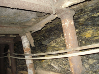
Table 3). However, significantly increased cracking and disintegration in some isolation walls was observed as a result of the mechanical action of the air currents. The mechanical effect of air currents is manifested in such a way that due to the decrease in humidity and drying of the contact parts of the isolation walls towards the fresh air current, their partial mechanical destruction occurs. This is most noticeable by observing the isolation walls towards the fresh and return air currents (
Figures 3 and 4).
Figure 3. Isolation wall located towards the fresh air stream (the consequences of mechanical action are visible).
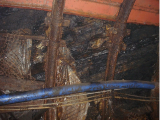
Figure 4. Isolation wall located towards the return air stream (no consequences of mechanical action).
Changes in gas ratios and pressure in the isolation walls were observed through the intensity of the release of individual gases into the wells from which samples of the isolation walls were taken over a certain period of time and the measured underpressure or overpressure in the sampling well (
Table 4). In this way, the condition of the sampling wells at locations (2), (4) and (6) was monitored. At location (1), due to the condition of the isolation wall, we could not hermetically seal the well, and locations (3) and (5) were not used because they correspond to the isolation walls included in locations (2) and (6). Based on the intensity of the release of individual gases, we can determine the condition of the isolation wall itself, its tendency to allow migration and movement of individual gases in the isolation wall itself or between the isolation wall and the mining room.
Table 4. Results of laboratory analysis of air from sampling wells.
Sample location | Analysis date (2025.g) | P1 (Pa) | P2 (Pa) | Ap (hPa) | Gas concentration |
O2 (%) | CO2 (%) | CO (ppm) | CH4 (%) |
2 | 26.04. | 0 | 0 | 985 | 3,07 | 0,65 | 1,1 | 77,13 |
17.05. | 0 | 0 | 977 | 3,17 | 0,75 | 2,1 | 75,45 |
12.06. | 0 | 0 | 971 | 3,53 | 0,80 | 2,6 | 75,45 |
14.07. | 0 | 0 | 983 | 4,34 | 0,98 | 2,1 | 64,92 |
16.08 | 0 | 0 | 978 | 3,65 | 1,2 | 2,7 | 65,76 |
13.09. | 0 | 0 | 981 | 5,62 | 1,3 | 3,1 | 52,87 |
22.10. | 0 | 0 | 978 | 7,75 | 1,03 | 2,3 | 49,60 |
16.11. | 0 | 0 | 974 | 11,15 | 1,1 | 3,5 | 36,46 |
17.12. | 0 | 0 | 973 | 11,85 | 1,1 | 3,3 | 33,49 |
4 | 26.04. | 0 | -12 | 985 | 2,46 | 4,76 | 1,2 | 3,19 |
17.05. | 0 | -7 | 977 | 1,7 | 5,4 | 1,8 | 2,92 |
12.06. | 0 | -3 | 971 | 0,99 | 5,5 | 1,9 | 3,21 |
14.07. | 0 | - 4 | 983 | 1,75 | 5,32 | 1,6 | 3,42 |
16.08 | 0 | - 6 | 978 | 1,55 | 5,51 | 2,1 | 3,27 |
13.09. | 0 | - 5 | 981 | 1,43 | 5,78 | 2,7 | 3,97 |
22.10. | 0 | - 4 | 978 | 1,29 | 5,33 | 2,4 | 4,13 |
16.11. | 0 | - 8 | 974 | 0,93 | 6,46 | 2,5 | 3,91 |
17.12. | 0 | - 7 | 973 | 1,02 | 6,23 | 2,2 | 3,86 |
6 | 26.04. | 0 | -18 | 985 | 8,07 | 3,69 | 0,8 | 2,28 |
17.05. | -5 | -12 | 977 | 5,85 | 4,47 | 2,0 | 3,2 |
12.06. | -4 | -11 | 971 | 5,27 | 4,83 | 2,2 | 3,17 |
14.07. | - 6 | - 15 | 983 | 5,45 | 4,67 | 1,9 | 3,87 |
16.08 | - 4 | - 10 | 978 | 4,89 | 5,1 | 2,3 | 3,6 |
13.09. | - 11 | - 19 | 981 | 5,03 | 4,9 | 2,5 | 3,97 |
22.10. | - 14 | - 18 | 978 | 5,02 | 5,00 | 2,7 | 2,87 |
16.11. | - 9 | - 20 | 974 | 4,95 | 5,83 | 2,1 | 3,58 |
17.12. | - 7 | - 16 | 973 | 4,66 | 5,31 | 2,6 | 4,23 |
P1 – Well pressure before air sampling (Pa)
P2 - The pressure in the well after taking the air sample (Pa)
Ap – Atmospheric pressure at the time of air sampling (hPa)
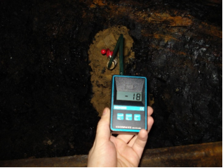
Figure 5. Pressure measurement in the sampling well.
3. Discussion
Changes in isolation walls as a function of the influence of the pit ventilation system and the time of their exploitation were examined through the moisture content in them
, porosity, depth of destruction and changes in gas ratios
| [16] | Z. Li, T. Ren, Y. Cheng and other: “Study of methane and carbon dioxide adsorption-desorption hysteresis in coals from Sydney Basin: A theoretical and experimental approach”, International Journal of Mining Science and Technology, Volume 34, Issue 10, October 2024, Pages 1453-1463,
https://doi.org/10.1016/j.ijmst.2024.09.008 |
[16]
.
The influence of the temperature and humidity of air currents is of crucial importance on the humidity of isolation walls. The higher the humidity of the air current, the higher the moisture content in the isolation wall. However, the influence of the temperature of air currents does not follow this law. Although warmer return air currents should affect the decrease in humidity in isolation walls, they do not. Moreover, cooler fresh air currents have a greater effect on the drying of isolation walls. Of course, from the point of view of thermodynamics, this makes no sense and should actually be the opposite, that is, with an increase in the temperature of air currents, the moisture content in isolation walls decreases. This would certainly be the case if there were no influence of the humidity of air currents. We conclude that the humidity of the air currents actually has a decisive influence on the moisture content in the isolation walls, whether or not the moisture content in the isolation walls will decrease depends on the moisture content in the air currents. In some cases, we also encounter the phenomenon that, due to the high moisture content in the air currents, we encounter condensed water vapor from the air in the form of droplets on the edges of the isolation walls. Based on the results of testing the moisture content in the samples of the isolation walls, we can safely conclude that the humidity of the air currents completely eliminates the influence of the temperature of the air currents on the isolation walls.
The change in the porosity of the protective isolation walls as a function of the position of the isolation walls in the pit ventilation system has not been proven. The pit ventilation system does not affect the porosity in the deeper parts of the isolation walls. The porosity remains the same as in the coal seam formation phase, but the moisture content and gases that fill these pores change.
The study of changes in gas ratios in isolation walls as a function of time was carried out on the basis of laboratory analysis of the air composition in the wells as well as changes in the potential (pressure) in them. Adsorbed gases from coal, which make up the natural gas bearing capacity of coal, are separated (desorbed) into the free volume of the drilled well due to the disruption of the equilibrium that prevailed between the adsorbed gas and coal
| [17] | W. Liu and other: “Evaluation of adsorbed and free gas in the coal matrix during desorption processes: Insights from experimental and numerical methods”, Fuel, Volume 376, November 2024., https://doi.org/10.1016/j.fuel.2024.132739 |
[17]
. Desorption of gases lasts until a new dynamic equilibrium between gas and coal is established.
The intensity of gas desorption primarily depends on the coal layer. In place of the desorbed gas, oxygen is adsorbed, which enters the free space of the well from the mine air. This adsorption is in the first phase of a physical nature and is the result of oxygen binding to the free surface by weak Van der Waals attractive forces
. Over time, chemisorption occurs, a chemical reaction between coal and oxygen, which results in the formation of carbon monoxide. The intensity and rate of carbon monoxide formation and oxygen adsorption depend on the properties of the coal in the isolation walls. The content of oxygen and carbon monoxide in air samples from wells tells us that the coal in the isolation walls actually performs its adsorption, which partially turns into chemisorption. Carbon dioxide (CO
2) appears in wells as a result of desorption from the isolation walls. In the isolation walls, the gas can be free, filling pores and cracks, adsorbed or absorbed. The content of carbon dioxide in air samples from wells increases over time.
Methane (CH4) in wells is formed due to separation from pores as a free gas or due to desorption from the coal layer or isolation walls. The content of methane in air samples from wells actually has very different values.
Figure 6. Methane concentration in sampling wells.
Based on
Figure 6 and
Table 4, a huge difference in methane content between well (2) and the other two wells can be seen. According to Chodot
| [19] | W. W. Chodat: “The influence of humidity on the methane content of coal seams”, OTN., 1952., 97-102. |
[19]
, coal moisture reduces the sorption volume of coal by as much as three times, and according to J. L. Ettinger
| [20] | J. L. Ettinger: “Physical chemistry with the gas content of coal seams”, Nauka, Moskva 1981. |
[20]
, an increase in temperature reduces the amount of adsorbed methane. Based on these studies, and on the conditions related to sampling well (2), it is possible to explain the reasons for such high methane concentrations. The isolation wall sample from well (2) has the lowest level of natural moisture, while the temperature next to this well is the lowest compared to the other two.
What may also be interesting, based on the data in
Table 4, is the pressure value in the wells. The volume of the wells is about 40 (l) and an air sample is taken from them into a rubber ball of volume 2 (l) by suction. In this way, a certain negative pressure is achieved in the well itself. By measuring its value, it was determined that in well number (2) it has a constant value of 0 (Pa). This means that although the well is hermetically sealed through a isolation wall, and due to its cracks and moisture loss, there is a constant and free path for air to pass in and out of the well. This free passage through the cracks is so clear that it instantly cancels the pressure drop caused by taking an air sample. In well (4), it takes a certain amount of time for the pressure in the well and in the free profile of the room to equalize. This indicates that there is a certain isolation and level of hermeticity between the well and the free profile of the room. The most interesting results were obtained by measuring the pressure in well (6). Since the first air sample was taken from this well, the pressure in it has no longer equalized with that in the room and the pressure difference varies and mainly depends on the atmospheric pressure. This indicates that there is satisfactory hermeticity between the well and the free profile of the room. Since the location of borehole (6) is in the outlet air flow room, it is obvious that in this zone there was no release of moisture from the protective pillar, moisture still fills all the pores and cracks in the isolation walls and thus prevents free passage between the sampling borehole and the mining room profile.
4. Conclusion
Based on the research results, the following was determined:
1. The humidity of the isolation wall changes under the influence of the pit ventilation system. Air currents have a dual effect on the isolation walls in terms of changing their humidity.
The fresh air current from the isolation wall absorbs a certain amount of moisture, carries it outside through the ventilation system, and thus reduces the moisture content in the isolation walls. The absorption of moisture from the isolation walls by the fresh air current is most pronounced on the contact surface of the isolation wall and the free profile of the mining room. The intensity of the “drying” of the isolation walls in this zone is so pronounced that due to the reduction or loss of cohesive and adhesive forces in the isolation wall, we encounter the appearance of a zone of its decomposition. The depth of the zone of decomposition of the isolation wall in our case is up to 2.5 (m).
The outgoing air stream, itself extremely humid, is not able to take on additional moisture from the isolation walls. Moreover, it transfers a certain amount of moisture to the isolation walls, which we can easily detect through condensed water drops on the edges of the isolation walls. Because there is no decrease in moisture, the cohesive and adhesive forces are still sTable, there are no decomposition zones on these isolation walls, and the contact surface between the isolation wall and the free profile of the mining room is regular.
The influence of the temperature of the air currents on the change in the humidity of the isolation walls has also been determined. However, with pronounced humidity of the air currents, the influence of temperature on changes in the isolation walls from the aspect of changing their humidity is eliminated. This certainly does not have to be the rule if the humidity of the air currents is not high and it needs to be investigated for such conditions.
2. Gas ratios in the isolation walls change as adsorbed and free gas migrates from the isolation walls under pressure or diffusion through desorption. Gas from the isolation walls migrates and moves much faster than moisture, moisture filling the pores and cracks prevents gas migration. By releasing moisture from the pores and cracks of the isolation walls, conditions are created for the movement of gas towards the free profile of the mining premises, for the degassing of the isolation walls. This process is continuous and the amount of released (desorbed) gas decreases over time.
Gas ratios in the isolation walls also change based on certain chemical processes represented by chemisorption.
3. It has been established that the pit ventilation system does not necessarily cause rheological changes in the isolation walls. Rheological changes were determined for isolation walls located towards the fresh air flow. The intensity of rheological changes in isolation walls depends on the time of exploitation of the isolation wall, the speed and humidity of air currents.
4. If the service life of the isolation wall will be a longer period of time, several years, and if it is formed in the premises of the incoming air stream, then based on the research results, changes in its design are also proposed. That is, it is necessary to increase its width precisely by the expected size of the decomposition zone.
Author Contributions
Safer Demirović: Data curation, Investigation, Methodology, Writing – original draft
Jelena Marković: Formal Analysis, Writing – review & editing
Conflicts of Interest
The authors declare that they have no known competing financial interests or personal relationships that could have appeared to influence the work reported in this paper.
References
| [1] |
T. Yang, Y. Zhang and other: “Study on the Stability and Reasonable Width of Coal Pillars in “Three Soft” Coal Seams Based on a Physical Similarity Simulation Experiment”, Applied Sciences, Volume 14, Issue 14, 2024.,
https://doi.org/10.3390/app14146127
|
| [2] |
L. Dai, H. Lei, X. Cheng, R. Li: “Prediction of coal seam gas content based on the correlation between gas basic parameters and coal quality indexes”, Frontiers Energy Research, Volume 10, 2022.,
https://doi.org/10.3389/fenrg.2022.1096539
|
| [3] |
J. Marković, S. Mićević: “Požari u rudnicima uglja” [Fires in coal mines], UNTZ, Tuzla 2005.
|
| [4] |
V. R. Sastry: “Stress distribution on longwall barrier pillar due to goaf formation during extraction”, Journal of the Institution of Engineers, India, Mining Engineering Division, 2009.
|
| [5] |
Z. Benjavski: ” Upravlenie gornim davleniem”, Moskva 1990.
|
| [6] |
G. York, I. Canbulat, B. W. Jack: “Coal pillar design procedures”, Safety in Mines Research Advisory Committee, Mine Health and Safetv Council, March 2000.
|
| [7] |
R. N. Singh, A. G. Pathan, B. Unver: “Design of rib pillars in longwall mining based on theoretical and practical approaches”, Maden Muhendisleri Odasi, 1987.
|
| [8] |
H. Wagner: “Pillar design in coal mines”, Journal of the South African Institute of Mining and Metallurgy, January 1980., 37-45.
|
| [9] |
J. N. van der Merwe: “Develop intrnational links for co-operative research in coal mining with special emphasis on interaction with international experts for developing industry guidelines for the design of pillars in coal mines”, Safety in Mines Research Advisory Committee, Mine Health and Safetv Council, July 2001.
|
| [10] |
J. M. Galvin, B. K. Hebblewhite, M. D. G. Salamon: “University Of New South Wales Coal Pillar Strength Determinations For Australian And South African Mining Conditions”, National Institute for Occupational Safety and Health (NIOSH), CDC STACKS, 1999.
|
| [11] |
Z. T. Bieniawski: “A method revisited: coal pillar strength formula based on field investigations”, Proceedings of the workshop on coal pillar mechanics and design, US Bureau of Mines IC 9315 1992.
|
| [12] |
J. N. van der Merwe: “New pillar strength formula for South African coal”, Journal of the South African Institute of Mining and Metallurgy, June 2003., 281-292.
|
| [13] |
K. Oraee, N. Hosseini, H. Yasipur: “Logical design of yield pillar base in longwall mining”, Seventeenth international symposium on mine planning and equipment section, Beijing, China, 2008.
|
| [14] |
E. Ghasemi, K. Shahriar: “A new coal pillars design method in order to enhance safety of the retreat mining in room and pillar mines”, Safety Science, Volume 50, Issue 3, March 2012, Pages 579-585,
https://doi.org/10.1016/j.ssci.2011.11.005
|
| [15] |
M. Gao, Y. Liu: “Experimental Study on the Influence of Moisture Content on the Mechanical Properties of Coal”, Geofluids, August 2021,
https://doi.org/10.1155/2021/6007410
|
| [16] |
Z. Li, T. Ren, Y. Cheng and other: “Study of methane and carbon dioxide adsorption-desorption hysteresis in coals from Sydney Basin: A theoretical and experimental approach”, International Journal of Mining Science and Technology, Volume 34, Issue 10, October 2024, Pages 1453-1463,
https://doi.org/10.1016/j.ijmst.2024.09.008
|
| [17] |
W. Liu and other: “Evaluation of adsorbed and free gas in the coal matrix during desorption processes: Insights from experimental and numerical methods”, Fuel, Volume 376, November 2024.,
https://doi.org/10.1016/j.fuel.2024.132739
|
| [18] |
Q. Li and other: “A mathematic model based on eDLVO and Lifshitz theory calculating interparticle interactions in coal water slurry”, Fuel, Volume 316, May 2022.,
https://doi.org/10.1016/j.fuel.2022.123271
|
| [19] |
W. W. Chodat: “The influence of humidity on the methane content of coal seams”, OTN., 1952., 97-102.
|
| [20] |
J. L. Ettinger: “Physical chemistry with the gas content of coal seams”, Nauka, Moskva 1981.
|
Cite This Article
-
APA Style
Demirović, S., Marković, J. (2026). The Impact of Pit Ventilation System on Protective Isolation Walls in Coal Mine. International Journal of Oil, Gas and Coal Engineering, 14(2), 17-26. https://doi.org/10.11648/j.ogce.20261402.11
 Copy
|
Copy
|
 Download
ACS Style
Demirović, S.; Marković, J. The Impact of Pit Ventilation System on Protective Isolation Walls in Coal Mine. Int. J. Oil Gas Coal Eng. 2026, 14(2), 17-26. doi: 10.11648/j.ogce.20261402.11
Copy
|
Download
AMA Style
Demirović S, Marković J. The Impact of Pit Ventilation System on Protective Isolation Walls in Coal Mine. Int J Oil Gas Coal Eng. 2026;14(2):17-26. doi: 10.11648/j.ogce.20261402.11
Copy
|
Download
-
@article{10.11648/j.ogce.20261402.11,
  author = {Safer Demirović and Jelena Marković},
  title = {The Impact of Pit Ventilation System on Protective Isolation Walls in Coal Mine},
  journal = {International Journal of Oil, Gas and Coal Engineering},
  volume = {14},
  number = {2},
  pages = {17-26},
  doi = {10.11648/j.ogce.20261402.11},
  url = {https://doi.org/10.11648/j.ogce.20261402.11},
  eprint = {https://article.sciencepublishinggroup.com/pdf/10.11648.j.ogce.20261402.11},
  abstract = {Underground coal mining is impossible without the use of protective pillars or protective isolation walls. Regardless of the method of coal mining (longwall method, room and pillar etc.), they all require the use of pillars or protective isolation walls. Their application is present in the exploitation of all types of coal. Today, the design of pillars and protective isolation walls is carried out in the same way. All of them, regardless of their physical and mechanical properties or the applied excavation method, undergo changes over time. Changes can occur due to mechanical damage (mining, rockfall, vibrations due to transport, gas outbursts, etc.) or due to the influence of the pit ventilation system. Although the influence of the ventilation system of the pit on the protective insulation walls is established and known, it has been very little addressed and treated in the literature or concrete research. After the formation of a pillar or isolation wall, under the influence of the pit ventilation system, moisture and gases begin to be released from it, and the cohesive and adhesive forces in it weaken, which also leads to rheological changes. It has been established that in isolation walls where moisture is periodically or constantly introduced and increased for some reason, most often in order to eliminate coal dust, the intensity of rheological changes is lower than in those where this is not done. The paper presents the results of research into the changes that occurred in protective insulating walls used in brown coal mining due to the influence of the pit ventilation system over a certain period of time. Changes in the design of protective columns and insulating walls, taking into account the influence of the pit ventilation system on them, are also proposed.},
 year = {2026}
}
Copy
|
Download
-
TY  - JOUR
T1  - The Impact of Pit Ventilation System on Protective Isolation Walls in Coal Mine
AU  - Safer Demirović
AU  - Jelena Marković
Y1  - 2026/04/30
PY  - 2026
N1  - https://doi.org/10.11648/j.ogce.20261402.11
DO  - 10.11648/j.ogce.20261402.11
T2  - International Journal of Oil, Gas and Coal Engineering
JF  - International Journal of Oil, Gas and Coal Engineering
JO  - International Journal of Oil, Gas and Coal Engineering
SP  - 17
EP  - 26
PB  - Science Publishing Group
SN  - 2376-7677
UR  - https://doi.org/10.11648/j.ogce.20261402.11
AB  - Underground coal mining is impossible without the use of protective pillars or protective isolation walls. Regardless of the method of coal mining (longwall method, room and pillar etc.), they all require the use of pillars or protective isolation walls. Their application is present in the exploitation of all types of coal. Today, the design of pillars and protective isolation walls is carried out in the same way. All of them, regardless of their physical and mechanical properties or the applied excavation method, undergo changes over time. Changes can occur due to mechanical damage (mining, rockfall, vibrations due to transport, gas outbursts, etc.) or due to the influence of the pit ventilation system. Although the influence of the ventilation system of the pit on the protective insulation walls is established and known, it has been very little addressed and treated in the literature or concrete research. After the formation of a pillar or isolation wall, under the influence of the pit ventilation system, moisture and gases begin to be released from it, and the cohesive and adhesive forces in it weaken, which also leads to rheological changes. It has been established that in isolation walls where moisture is periodically or constantly introduced and increased for some reason, most often in order to eliminate coal dust, the intensity of rheological changes is lower than in those where this is not done. The paper presents the results of research into the changes that occurred in protective insulating walls used in brown coal mining due to the influence of the pit ventilation system over a certain period of time. Changes in the design of protective columns and insulating walls, taking into account the influence of the pit ventilation system on them, are also proposed.
VL  - 14
IS  - 2
ER  -
Copy
|
Download